UTLK - CHAPTER 2 Memory Addressing
30 Apr 2018Note: The subtitles in this chapter are reorganized for the ease of my own understanding. I find them more logically ordered this way than they are in the book.
- Memory Addresses
- Paging in Hardware
- Page, Page Frame and Page Table
- Regular Paging
- Page Directory/Table Data Structure
- Extended Paging
- Hardware Protection Scheme
- Physical Address Extension (PAE) Paging Mechanism
- Paging for 64-bit Architectures
- Hardware Cache
- Translation Lookaside Buffers (TLB)
- Paging in Linux
- The Linear Address Fields
- Page Table Handling
- Physical Memory Layout
- Process Page Tables
- Kernel Page Tables
- Provisional kernel Page Tables
- Final kernel Page Table when RAM size is less than 896MB
- Final kernel Page Table when RAM size is between 896MB and 4096MB
- Final kernel Page Table when RAM size is more than 4096MB
- Handling the Hardware Cache and the TLB
Memory Addresses
This chapter focuses on the Intel 80x86 microprocessor memory addressing techniques, but they should generally apply to most other processors too.
At the highest level, you have a great amount of memory cells that can be used to store instructions to be executed by the CPU and data to be read by the CPU. You need to tell the CPU how to access the contents of each cell so you give them “addresses”, just like every house in America has an address so mails can be delivered. Each memory address typically points to a single byte in memory.
Segmentation
Intel thinks it is a good idea to split a big program into small logical segments, each to store partial information about the program. For example, there can be a code segment for compiled instructions of the program, while all global and static variables may reside a separate segment called the data segment. Similarly, there can be stack segment designated for a process’ stack at runtime. This, when applied to the address space of a running process, splits the entire memory into multiple segments too, each consists of a chunk of addresses.
Segment Selector
With segmentation, to address a memory location, a pair of identifiers are used:
(Segmentation Selector, Offset). Segmentation Selector is a 16-bit number that
identifies which of the many segments this address lies in, and “Offset” tells
the distance from the start of the selected segment.
Segment Descriptor
Other than a base address, to precisely describe a segment, at least its “size” needs to be known. There are other characteristics of a segment that the kernel finds useful, such as which privilege level is required to access addresses in a segment’s range, is the segment for data or code, etc. These details together, are stored in a data structure called the Segmentation Descriptor.
Global Descriptor Table (GDT) and Local Descriptor Table (LDT)
Now that we have a set of segments, each with its descriptor, we need an array to store all these descriptors. This array is called a Descriptor Table. There is usually a Global Descriptor Table or GDT that’s shared by all processes (they use the same segments for addressing), and optionally a per-process table called the Local Descriptor Table.
Both tables are stored in memory themselves. To locate them, their addresses are
stored in two registers: gdtr and ldtr, respectively.
Logical Address and Linear Address
In Intel’s design, all addresses used in programs should be “Logical Addresses”,
which are (Segmentation Selector, Offset) pairs. But the CPU doesn’t
understand these pairs, so there is a designated hardware component that
translates logical addresses into Linear Addresses, which are 32-bit
unsigned integers that range from 0x00000000 to 0xffffffff, for a memory of 4
gig bytes. This hardware component is called the Segmentation Unit.
Segmentation Unit
Segmentation unit’s sole purpose is to translate logical addresses into linear
addresses. It takes a (Segment Selector, Offset) pair, from which it gets the
index into the Descriptor Table (array) of the segment to select, which then
gives the starting (base) address of that segment. Then by multiplying Offset by
8 (each descriptor in the Descriptor Table is 8-byte long) and adding the
product to the base, it gets a linear address.
Fast Address Translation
As you can see from above section, each address translation involves one read of the Descriptor Table (to get the descriptor of the selected segment), which sits in memory. Because the descriptor of a segment rarely changes, it’s possible to speed up translations by loading the descriptor (8 byte) into a dedicated register, so subsequent translations don’t need to read memory, which is a magnitude slower than reading a register.
Segmentation in Linux
Though the concept of segmentation and splitting programs into logically related chunks is kind of enforced by Intel processors, Linux doesn’t use segmentation much. In fact, it defines barely a handful of segments even though the maximum allowed number is 2^13 (13-bit used for index in Segment Selector).
Four main segments Linux uses are: Kernel Code Segment, Kernel Data Segment,
User Code Segment, and User Data Segment. The Segment Selector values of these
are defined by the macros __KERNEL_CS, __KERNEL_DS, __USER_CS and
__USER_DS. To address the kernel code segment, for example, the kernel simply
loads the value defined by __KERNEL_CS into the segmentation register.
The descriptors of each segment are as follows:
| Segment | Base | G | Limit | S | Type | DPL | D/B | P |
|---|---|---|---|---|---|---|---|---|
| user code | 0x00000000 | 1 | 0xffff | 1 | 10 | 3 | 1 | 1 |
| user data | 0x00000000 | 1 | 0xffff | 1 | 2 | 3 | 1 | 1 |
| kernel code | 0x00000000 | 1 | 0xffff | 1 | 10 | 0 | 1 | 1 |
| kernel data | 0x00000000 | 1 | 0xffff | 1 | 2 | 0 | 1 | 1 |
As you can see all four segments start at address 0. This is not a mistake. In Linux, a logical address always coincides with a linear address. Again, Linux is not a big fan of segmentation and spends more of its design in an alternative paging mechanism - paging - which we will talk about next.
The Linux GDT
As mentioned above, the GDT is an array of Segment Descriptor structs. In Linux,
the array is defined as cpu_gdt_table, while the address and size of it are
defined in the cpu_gdt_descr array. It is an array because there can be
multiple GDTs: on multi-processor systems each CPU has a GDT. These values are
used to initialize the gdtr register.
Both arrays are 32-element long, which include 18 valid segment descriptors, and 14 null, unused or reserved entries. Unused entries are there so that segment descriptors accessed together are kept in the 32-byte hardware cache line.
The Linux LDTs
These are similar to GDTs and are not commonly used by Linux applications except for those that run Windows applications, e.g., Wine.
Paging in Hardware
Just as the segmentation unit translates logical addresses into linear addresses, another hardware unit, the paging unit, translates linear addresses into physical addresses.
Page, Page Frame and Page Table
For efficiency, linear addresses are grouped into fixed-length chunks called pages. Contiguous linear addresses are mapped into contiguous physical addresses. Each of these groups is called a physical page frame. Note that while pages are blocks of data, page frames are physical constitute of the main memory.
The data structure that maps pages to page frames is called page table.
Regular Paging
The word “regular” is relative to the extended or more advanced paging techniques that are required for special cases that we will cover later in this chapter. This section is about the fundamental idea of how paging is done in Intel hardware.
As previously mentioned, the paging unit translates pages as the smallest unit and not individual addresses. The default page size on Linux is 4KB (2^12 bytes). So the 20 most significant bits of a 32-bit address alone can uniquely identify a page (the last 12 bits will be within a page). An rudimentary idea of implementing paging would be to have a table of (linear page, physical page) tuples, and try to match the 20 most significant bits of a linear address in the table. However, that implies that we would need 2^20 entries in the array, or at least reserve space for that many entries if the implementation is a linear array, even when the process doesn’t use all addresses in the range. With each entry taking up 4 bytes (32 bits), our table would take 4MB of memory. Of course there is room for improvement.
The idea is to split the 20 most significant bits into two 10-bit segments; the first 10 to be used as index to a higher level Page Directory whose entries are physical addresses to secondary Page Tables, and the rest 10 bits as index to a particular Page Table. With demand paging (page frames are only assigned when actually requested), the secondary Page Tables are added as the process requests more memory. In the extreme case that the process uses all 4GB address space, the total RAM used for the Page Directory and all Page Tables will be 4MB, no more than the basic algorithm above.
This is called 2-level paging and you will see the idea getting generalized into multi-level paging on systems with bigger address spaces, e.g., 64 bit systems.
The physical address of the Page Directory is stored in cr3. From there the
paging unit gets the physical address to a Page Table, and in turn it gets the
physical address of a page frame a page is mapped into. Then by adding the least
significant 12 bits of a linear address (Offset), it gets a 32 bit physical
address.
Page Directory/Table Data Structure
In Linux, it is a 32-bit compound integer of the following bits:
Present flag. If set, the referred-to page or page table is in main memory. If
not, the linear address requested is saved to cr2 and exception 14 (Page
Fault) is generated. The kernel relies on page faults to assign additional page
frames to a process.
20 most significant bits of a page frame physical address. Because of the 4KB page size, the last 12 bits of a physical address doesn’t matter.
Accessed flag. Whether or not the referred-to page or page table is accessed. This flag may be used to decide which pages to swap out in case the system is running low on memory.
Dirty flag. Whether or not the referred-to page or page table is written to. Similar use as the accessed flag.
Read/Write flag. Access right of the page frame or page table: read-only or writable.
User/Supervisor flag. Privilege needed to access the page or page table: user process or kernel.
PCD and PWT flags. Controls some hardware cache behaviors. Explained below at “Hardware Cache”.
Page Size flag. Controls the page size, if not 4KB. See “Extended Paging” for details.
Global flag. Controls TLB flush behaviors.
Extended Paging
On newer 80x86 processors, larger pages are supported (4MB instead of 4KB) and thus more bits are needed for the Offset part and fewer for Page Directory and Page Table. In fact, since the Offset takes 22 bits, the 10 most significant bits all be used as an index into the Page Directory, thus eliminating the need for secondary Page Tables.
Hardware Protection Scheme
Different from the segmentation unit, which allow multiple privilege levels (0, 1, 2, 3), the paging unit only allows two: User/Supervisor. Furthermore, only two rights are associated with pages: Read/Write.
Physical Address Extension (PAE) Paging Mechanism
The amount of RAM supported by a processor is limited by the number of address pins connected to the address bus. As the servers grow, Intel extended the address pins of their 80x86 processors from 32 to 36. This makes them able to address up to 2^36 = 64GB memory. Adapting to this change, Linux tweaked the number of bits used to index Page Directory, Page Table and as Offset, and in some cases, added an additional table before Page Directory - Page Directory Pointer Table. But the same general idea applies.
Paging for 64-bit Architectures
On 64-bi systems, there are 64 address pins. It certainly doesn’t make sense to use all 64-12 = 52 most significant bits (assuming a usual page size of 4KB) as that would give a maximum of 256TB address space! So fewer bits are used, and multi-level paging is used. The actual split of bits varies from architecture to architecture.
Hardware Cache
Typical RAMs access time is in the order of hundreds of clock cycles. That is a LOT of time comparing to instruction executions. To remedy the huge speed mismatch between the CPU and the memory, fast hardware cache memories are introduced. Based on locality principle, data recently fetched from memory, or those next to them, are kept in the cache. And over the years, multiple levels of cache are added, each with different speed and cost characteristics.
A new unit was introduced along with the hardware cache: line. It refers to a certain block of contiguous data in memory or in cache. Data are always read into cache or cleared in multiple of line. A line is usually several dozens of bytes.
On multi-processor systems, each CPU has its own hardware cache. The synchronization between two caches is important, and usually is done by a dedicated hardware unit so the OS doesn’t have to care. But one interesting feature of some cache is that the hardware allows the cache sync policy (Write-Through v.s. Write-Back) to be selected and set by the OS. In Linux, Write-Back is always selected.
Translation Lookaside Buffers (TLB)
Besides general purpose cache, 80x86 processors include another cache called the Translation Lookaside Buffer (TLB), to speed up linear address translation. When a linear address is used for the first time, the corresponding physical address is computed through page table lookups, and stored in the TLB for future reference. Note that because each process has its own page tables, the TLB is flushed during a context switch.
On multi-processor systems, each CPU has its own TLB. Unlike hardware cache, two TLBs don’t need to be synchronized because they are being used by two processes that have different page tables any way.
Paging in Linux
Linux adopts a common paging model that fits both 32-bit and 64-bit architectures. A four-level paging model is used, and consists of the following:
- Page Global Directory
- Page Upper Directory
- Page Middle Directory
- Page Table
For 32-bit architectures, two paging levels are sufficient so the Page Upper Directory and Page Middle Directory are eliminated - by saying that they contain zero bits.
Linux’s handling of processes relies heavily on paging. The automatic linear to physical address translation makes a few design objectives feasible:
- Assign a different physical address space to each process, ensuring isolation.
- Distinguish pages from page frames. This allows the same page to be written to a page frame, or swapped to disk, and then read back into memory at a different page frame.
Process Switch. The essence of process switch is saving the value of cr3
into the old process’ descriptor, and loading the new process’ Page Global
Directory physical address into cr3.
The Linear Address Fields
This and the following section (Page Table Handling) detail a few important macros and functions related to the Page Table data structures. I did not read them line by line and thus don’t have a lot to note down. I can always come back to them when needed.
Page Table Handling
Ditto.
Physical Memory Layout
This is the fun part about memory management. To start managing memory, the kernel first needs to know where all the memory chunks are, and how big each is. Note that not all physical memory is usable by the kernel. Some of them may be reserved by the BIOS, some reserved for IO device memory mapping, for example. In general, the kernel considers the following reserved (that cannot be dynamically assigned or swapped to disk):
- Those falling in the “unavailable” physical address ranges
- Those containing the kernel’s own code and data
Kernel address. In general, the Linux kernel is installed in RAM starting from the physical address 0x00100000 - i.e., from the second megabyte. The total number of page frames required depends on the configuration, but typically a Linux kernel image can fit in 3MB of memory.
Why is the kernel not loaded to the first megabyte?:
- Page frame 0 is used by BIOS to store system hardware configurations during its Power-On Self-Test (POST).
- Physical address 0x000a0000 to 0x000fffff are usually reserved for BIOS routines amd to map internal memory of ISA grapic cards.
- Additional frames within the first megabyte may be reserved by specific computer models.
During boot, the kernel queries BIOS to learn the size of the physical memory,
and the list of physical address ranges. It does this in the
machine_specific_memory_setup() function. Right after this, in the
setup_memory() function, it establishes the following variables:
| Variable name | Description |
|---|---|
| num_phypages | Page frame number of the highest usable page frame |
TODO: Fill the table.
Figure 2-13 shows how the first 3MB of RAM are filled by Linux.
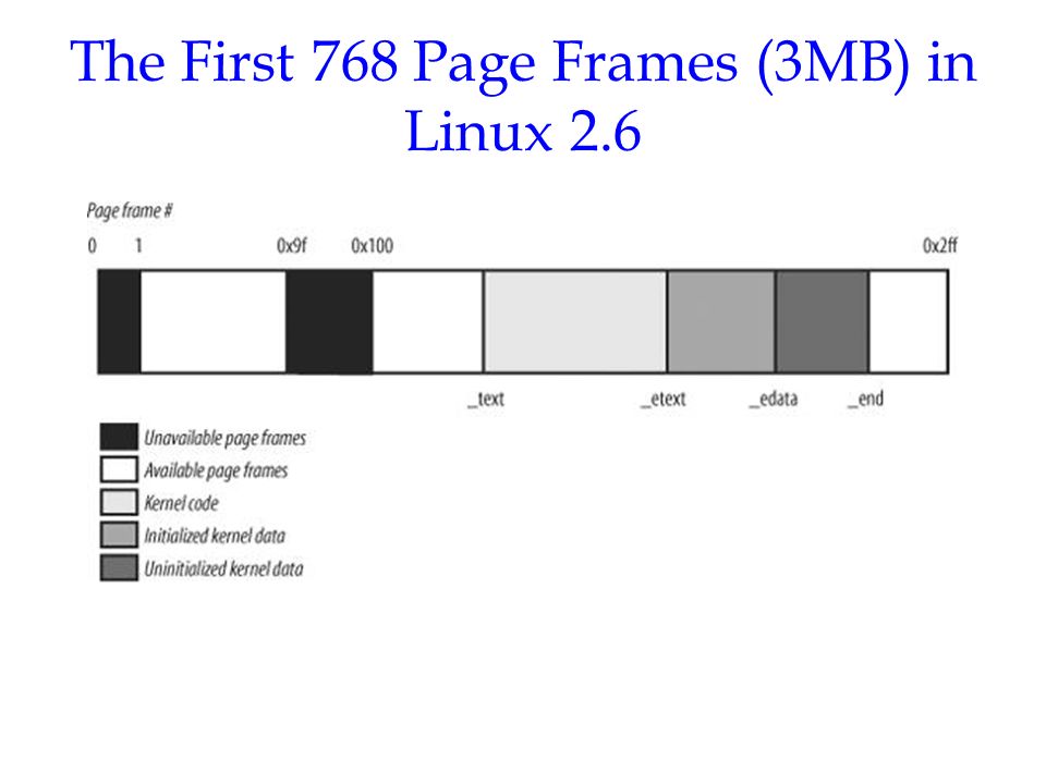
Starting at the physical address 0x00100000 is the symbol _text, which is the
address of the first byte of kernel code. Following it there are _etext,
_edata, and _end. They denote: end of text, end of data, and end of kernel.
Between _etext and e_data is the initialized data structures, and the next
is uninitialized data.
Process Page Tables
A process’ linear address space is divided into two parts:
- User or kernel mode: 0x00000000 to 0xbfffffff
- Kernel mode only: 0xc0000000 to 0xffffffff I.e., the lowest 896MB are pages used for kernel code and data.
Every process has a different Page Global Directory with different entries, but all of them share the entries for the lowest 896MB of linear address space - kernel.
Kernel Page Tables
The kernel maintains a set of page tables of its own, rooted at a master kernel Page Global Director. After system initialization, this set of page tables is never directly used by any process or kernel thread.
Chapter 8 will explain how the kernel ensures changes to the master kernel Page Global Directory always reflect in each process’ Page Global Directory. This chapter will next explain how the kernel initializes its own page tables. It is a two-phase activity, and note that right after when kernel is loaded into memory, the CPU is running in real mode, with paging disabled.
In the first phase the kernel creates a limited address space including kernel’s code and data segments, the initial Page Tables, and 128KB for some dynamic data structures.
In the second phase, the kernel sets up Page Tables for all of the existing RAM.
Provisional kernel Page Tables
A provisional Page Global Directory is initialized during kernel compilation
time, while provisional Page Tables are initialized at runtime, by the
startup_32() assembly function defined in arch/i386/kernel/head.S.
The provisional Page Global Directory is contained in the swapper_pg_dir
variable. Again, this is computed at compile time and is known at run time. The
provisional Page Tables are stored starting from pg0, right after _end in
the kernel image. For simplicity, we will assume the kernel image, the
provisional Page Tables, plus the 128KB dynamic space can fit into the first 8MB
of RAM. In order to map 8MB of RAM, two Page Tables are required (??).
The objective here is to allow these 8MB of RAM to be addressed in both real mode and in protected mode. Therefore, a mapping from both the linear addresses 0x00000000 through 0x007fffff (first 8MB in real mode) and the linear addresses 0xc0000000 through 0xc07fffff (first 8GB in protected mode) is needed. In other words, the kernel during initialization can address the first 8MB of RAM by either linear addresses identical to the physical ones, or 8MB worth of linear addresses, starting from 0xc0000000.
Identity Mapping. The mapping of linear addresses 0x00000000 through 0x007fffff to the same physical addresses is usually referred to as Identity Mapping. It is important because most CPUs are pipelined; that is, multiple instructions spit by the CPU might be in action in multiple stages. As soon as the MMU/paging unit is turned on, some old instructions spit by CPU with physical addresses may be in flight. For them to work, the first 8MB RAM range needs to be mapped too. StackOverflow answer.
The kernel creates that mapping by filling all the swapper_pg_dir (the
provisional Page Global Directory) entries with zeroes, except for entries 0, 1,
0x300 and 0x301; the latter two entries span all linear addresses between
0xc0000000 and 0xc07fffff:
The address field of entries 0 and 0x300 is set to the physical address of
pg0 (the byte immediately following the _end symbol), while the address
field of entries 1 and 0x301 is set to the physical address of the page frame
following pg0. Again, two page tables are needed to map 8MB of RAM.
Final kernel Page Table when RAM size is less than 896MB
The final kernel Page Tables should map linear addresses from 0xc0000000 through 0xffffffff to physical addresses starting at 0x0.
Final kernel Page Table when RAM size is between 896MB and 4096MB
Final kernel Page Table when RAM size is more than 4096MB
Handling the Hardware Cache and the TLB
Handling the hardware cache
As mentioned earlier, hardware caches are addressed by cache lines. The
L1_CACHE_BYTES defines the size of the cache line. To optimize for cache
hit rate, the kernel does the following tricks when dealing with data
structures:
- Most frequently used fields are placed at the lower offset within a data structure, so that they can be cached in the same line. Compare this to ording fields alphabetically or in groups of types.
- When allocating a large set of data structures, the kernel tries to store each of them in memory in such a way that all cache lines are used uniformly.
Cache synchronization. As mentioned earlier, on 80x86 microprocessors hardware cache synchronization (between CPUs) are taken care of by the hardware and is transparent to the kernel.
Handling the TLB
Contrary to that, TLB flushes have to be done by the kernel because it is the kernel that decides when a mapping between a linear address and a physical address is no longer valid.
TLB synchronization between CPUs are done by the means of a Interprocessor Interrupts. That is, a CPU that is invalidating its TLB sends a signal to others to force them to do a flush as well.
Generally speaking, a process switch indicates a TLB flush. However there are a few exceptional cases in which a TLB flush is not necessary:
- When the switch is to another process that uses the same set of page tables as the process being switched from.
- When performing a switch between a user process and a kernel thread. That is because kernel threads do not have their own page tables; rather, they use the set of page tables owned by the user process that was scheduled last for execution on the CPU.
Lazy TLB flushes. We mentioned earlier that TLB synchronization is done through one CPU sending an Interprocessor Interrupt to others. When a CPU that is running a kernel thread gets such an interrupt, it simply ignores it and skips the requested TLB flush as kernel threads don’t access user processes’ address space (the lower 3GiB) - they won’t reference the TLB entries any way. This is called the lazy TLB mode. However, the kernel remembers that an interrupt has been received so when it switches back to a user process, it correctly issues the TLB flush.